
12
Nov
Welding symbols are an essential part of engineering drawings, fabrication blueprints, and construction plans. They communicate exactly how a welded joint should be prepared, where the weld must be placed, what type of weld is required, and which dimensions or finishing requirements must be followed.
For professional welders, metal fabricators, welding inspectors, engineers, and construction contractors, understanding these symbols is critical to completing projects accurately and consistently.
However, welding drawings can be confusing, particularly for beginners who are unfamiliar with reference lines, arrow-side designations, fillet weld symbols, groove weld symbols, and supplementary markings.
Whether you are working with structural steel, aluminum fabrication, stainless steel components, machinery repairs, or custom metalwork, learning how to read welding symbols can help prevent fabrication mistakes, reduce rework, and improve communication between everyone involved in a project.
This guide explains common welding symbols, their meanings, how to interpret welding drawings, and why accurate symbol interpretation matters in professional welding applications.
What Are Welding Symbols?
Welding symbols are standardized graphical instructions used on engineering drawings to communicate welding requirements. Instead of writing lengthy descriptions for every welded connection, engineers use symbols to provide essential information in a compact and consistent format.
A welding symbol can communicate:
- The type of weld required, such as a fillet, groove, plug, or slot weld.
- The location of the weld relative to the joint.
- Weld size, length, and spacing.
- Whether welding is required on one side or both sides.
- Whether the weld must extend around the entire joint.
- Required weld surface contours and finishing methods.
- Additional instructions, including welding processes and inspection requirements.
The American Welding Society (AWS) publishes AWS A2.4, Standard Symbols for Welding, Brazing, and Nondestructive Examination, which establishes a recognized system for communicating these requirements.
In Canada, welding drawings and project specifications may reference applicable CSA standards, AWS standards, engineering specifications, and project-specific requirements. Always confirm which standard governs the drawing before interpreting its symbols.
Why Are Welding Symbols Important?
Welding symbols are more than simple markings on a blueprint. They help ensure that the finished welded connection meets the design requirements.
Misinterpreting even one symbol can result in an incorrectly positioned weld, insufficient weld size, excessive welding, unnecessary material preparation, or costly rework.
Here are some important reasons welding symbols matter:
1. Accurate fabrication
Welding symbols tell fabricators what type of weld is required and where it needs to be applied. This helps ensure that components are assembled according to the approved design.
2. Structural reliability
For structural steel connections, the specified weld size, length, location, and configuration can directly affect the performance of the connection. Following the engineering requirements is essential.
3. Reduced project costs
Understanding welding drawings before starting work can prevent unnecessary material preparation, additional labour, incorrect weld placement, and fabrication delays.
4. Better communication
Engineers, welders, inspectors, project managers, and fabricators can use a common visual language to communicate welding requirements.
5. Quality control and inspection
Welding symbols can also specify inspection requirements, including nondestructive examination methods and the extent of testing.
Understanding the Basic Parts of a Welding Symbol
Before learning individual weld symbols, it is important to understand the basic components used in a welding symbol.
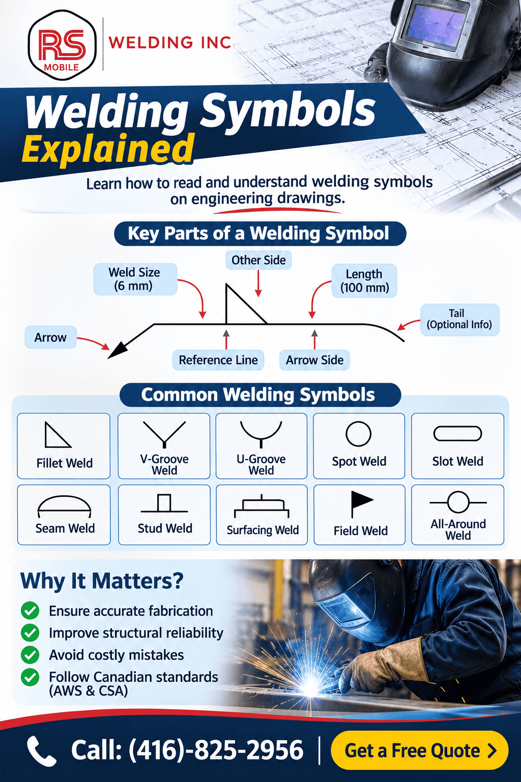
Under the AWS convention, the main elements include the arrow, reference line, and optional information such as the tail, weld symbol, dimensions, and supplementary markings.
1. Arrow
The arrow connects the welding symbol to the joint that requires welding.
It identifies the specific location of the connection on the engineering drawing. The arrow may point to a visible or hidden line, depending on the drawing requirements.
2. Reference Line
The reference line is the horizontal line on which the welding information is organized.
The weld symbol and its position relative to this line help identify the type of weld and which side of the joint requires welding.
3. Basic Weld Symbol
The basic weld symbol identifies the type of weld required.
For example, a triangular symbol represents a fillet weld, while different groove shapes identify different groove weld configurations.
4. Dimensions
Dimensions provide additional information about the weld, including:
- Weld size.
- Weld length.
- Spacing between intermittent welds.
- Groove depth and other joint preparation details.
The position of dimensions depends on the weld type and the applicable symbol convention.
5. Tail
The tail is an optional element located at the opposite end of the reference line from the arrow.
It can contain additional information, such as the welding process, reference to a welding procedure, applicable specifications, or other project instructions.
6. Supplementary Symbols
Supplementary symbols provide additional instructions about the required weld.
Examples include field weld symbols, all-around weld symbols, and weld contour markings.
Common Welding Symbols and Their Meanings
Different welding symbols represent different types of welded connections. Recognizing these symbols is one of the most important skills when reading fabrication drawings.
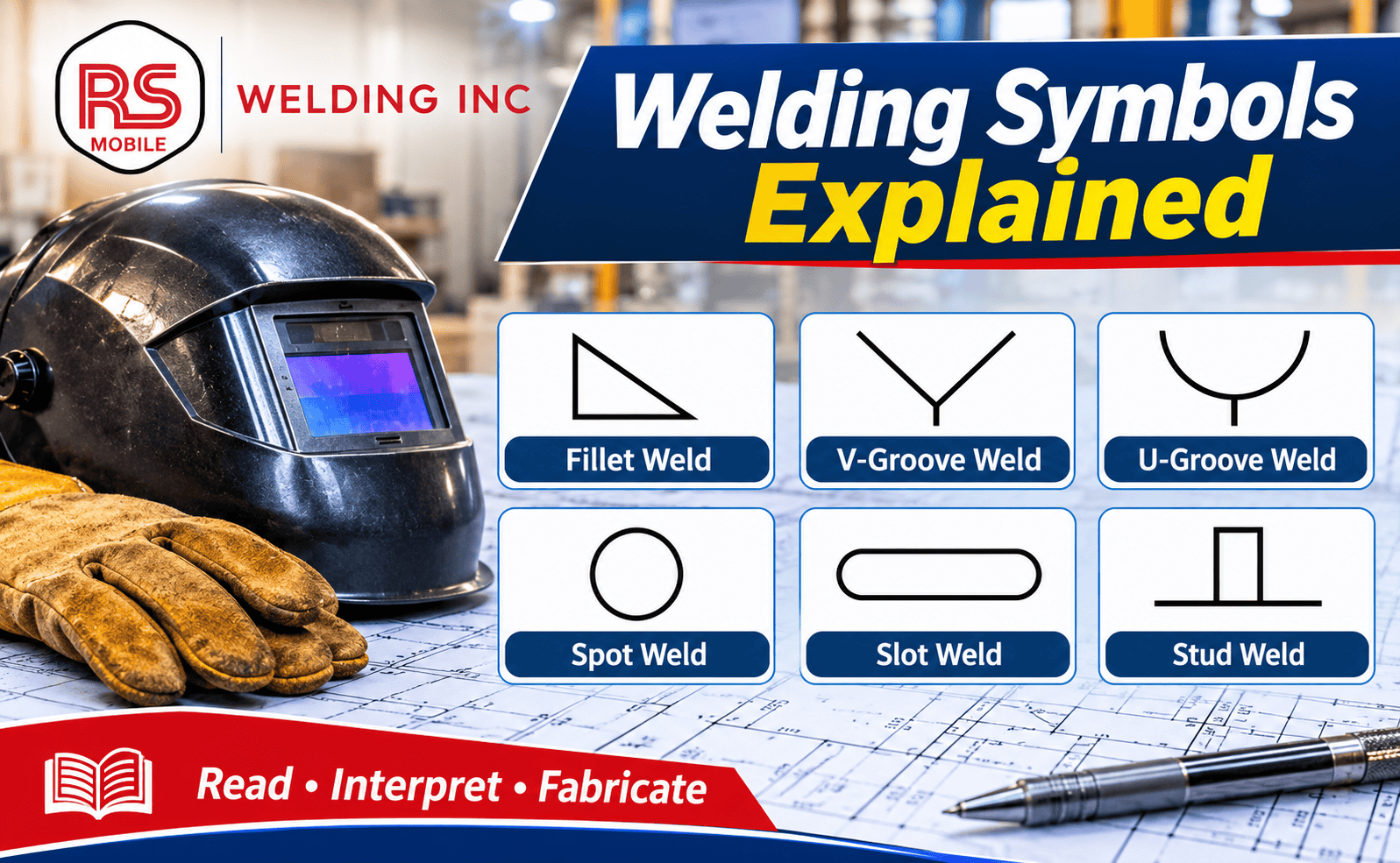
1. Fillet Weld Symbol
A fillet weld is one of the most commonly specified weld types in metal fabrication and structural welding.
It is generally used to connect two metal surfaces that meet at an angle, commonly in T-joints, lap joints, and corner joints.
The fillet weld symbol is represented by a triangle.
Common applications include:
- Structural steel frames and connections.
- Metal brackets and support plates.
- Steel railings and platforms.
- Equipment frames and mounting components.
- Custom gates and metal structures.
Fillet weld symbols may specify the weld size, length, spacing, and whether the weld is required on one or both sides of the joint.
2. Groove Weld Symbols
Groove welds are used when two metal components are joined along their edges, often with prepared joint surfaces.
They are particularly important in applications requiring specified penetration and joint strength.
Common groove weld symbols include:
- Square Groove Weld: Used when two edges are joined without a bevel or other groove preparation.
- V-Groove Weld: Both joining edges are prepared with an angle to create a V-shaped opening.
- Bevel Groove Weld: One member is prepared with a bevel while the other remains relatively square.
- U-Groove Weld: Both edges are prepared to form a rounded U-shaped groove.
- J-Groove Weld: One member has a J-shaped groove preparation.
- Flare-V Groove Weld: Used when joining curved or rounded surfaces that create a V-shaped opening.
- Flare-Bevel Groove Weld: Used when a rounded surface meets a flat surface, creating a curved groove configuration.
The drawing may also specify groove angle, root opening, depth of preparation, weld size, and backing requirements.
3. Plug Weld Symbol
A plug weld is used to join overlapping metal components through a circular hole in one component.
The hole is filled with weld metal to create a connection between the two pieces.
Typical applications include sheet metal fabrication, automotive components, and certain overlapping plate connections.
4. Slot Weld Symbol
A slot weld is similar to a plug weld, but the opening is elongated rather than circular.
It is commonly used in overlapping metal components where a longer welded connection is required through an opening.
5. Spot Weld Symbol
Spot welding is a resistance welding process used to create localized welds between overlapping metal sheets.
It is widely used in automotive manufacturing, sheet metal fabrication, and industrial production.
Spot weld symbols can communicate the required weld size, number of welds, spacing, and other specifications.
6. Seam Weld Symbol
Seam welding creates a continuous or specified intermittent welded connection along a joint.
It is commonly associated with resistance seam welding in sheet metal manufacturing and certain production applications.
7. Stud Weld Symbol
Stud welding attaches a metal stud or fastener to another metal surface through a specialized welding process.
Applications include construction, structural steel fabrication, and industrial equipment manufacturing.
8. Surfacing Weld Symbol
A surfacing weld is applied to a metal surface to restore dimensions, improve wear resistance, or provide a specific surface characteristic.
It is often used in heavy equipment repairs, industrial machinery maintenance, and component rebuilding.
9. Edge Weld Symbol
Edge welds join the edges of two or more metal components, generally where the parts are positioned alongside each other.
They may be used in sheet metal fabrication and other applications where the joint configuration permits an edge weld.
Understanding Arrow-Side and Other-Side Welding Symbols
One of the most important concepts when reading welding symbols is understanding the difference between the arrow side and the other side of a joint.
Under the AWS A2.4 convention:
- Arrow-side weld: The weld symbol is positioned below the reference line.
- Other-side weld: The weld symbol is positioned above the reference line.
- Both-side weld: Weld symbols appear both above and below the reference line.
For example, if a drawing shows a fillet weld symbol below the reference line, the welding requirement applies to the arrow side of the joint.
If the symbol appears above the reference line, it applies to the opposite side.
When fillet weld symbols appear on both sides, the drawing indicates that welding is required on both sides of the joint.
This distinction is especially important when fabricating steel frames, brackets, structural connections, and other assemblies where access to the joint may be limited.
Important: Always interpret the arrow in relation to the actual joint configuration. A double-sided symbol does not automatically mean welding on every visible surface of a component.
What Do Welding Symbol Dimensions Mean?
Weld dimensions provide the measurements required to complete a connection according to the drawing.
For fillet welds, the size is commonly indicated to the left of the weld symbol, while the weld length is generally indicated to the right.
For example, a drawing may specify a 6 mm fillet weld with a length of 100 mm.
This communicates the required fillet weld size and length, subject to the applicable drawing convention and specifications.
Other dimensions may include:
- Weld size: The specified size of the weld.
- Weld length: The length of the required weld.
- Pitch: The centre-to-centre spacing between intermittent welds.
- Groove angle: The specified angle of joint preparation.
- Root opening: The gap between the components before welding.
- Depth of preparation: The specified depth of the prepared groove.
Understanding these dimensions helps welders prepare materials correctly and follow the intended joint design.
Continuous vs. Intermittent Welding Symbols
Not every welded connection requires a continuous weld along its entire length.
Engineering drawings may specify either continuous or intermittent welding depending on the design requirements.
Continuous welds
A continuous weld extends along the specified joint length. It is commonly used where the design requires a continuous welded connection.
Intermittent welds
Intermittent welds consist of separate weld segments with specified lengths and spacing.
They may be used in certain structural and fabrication applications to control heat input, distortion, material usage, and fabrication time.
Intermittent welding symbols commonly include two dimensions:
- Weld segment length.
- Pitch, or centre-to-centre distance between successive weld segments.
Intermittent welds may also be specified in chain or staggered arrangements.
The actual weld arrangement must follow the engineering drawing rather than the fabricator’s assumptions.
Supplementary Welding Symbols You Should Know
In addition to basic weld symbols, engineering drawings may include supplementary markings that provide important instructions.
All-Around Weld Symbol
A small circle placed at the junction of the arrow and reference line indicates that the weld must extend all around the joint.
This marking is commonly used for tubular connections, brackets, and other components requiring a continuous weld around the specified joint.
Field Weld Symbol
A flag-shaped marking indicates that the weld is to be completed in the field rather than in the fabrication shop.
This is particularly relevant to construction projects involving structural steel installation and on-site assembly.
Flush, Convex, and Concave Contours
Contour markings indicate the required shape of the finished weld surface.
- Flush or flat contour: The weld surface must be finished flat or flush.
- Convex contour: The weld surface must have an outward-curved profile.
- Concave contour: The weld surface must have an inward-curved profile.
Additional finishing designations may specify how the contour is achieved, such as grinding or machining.
The required finish should not be assumed from appearance alone; the drawing and governing specification determine the requirement.
How to Read a Welding Symbol Step by Step
Understanding welding symbols becomes easier when you follow a consistent process.
Step 1: Identify the joint
Locate the arrow and determine which components or surfaces are being joined.
Step 2: Examine the reference line
Check where the welding symbol is positioned in relation to the reference line.
Determine whether the requirement applies to the arrow side, other side, or both sides.
Step 3: Identify the weld type
Look at the basic symbol to determine whether the connection requires a fillet, groove, plug, slot, spot, or another weld type.
Step 4: Check the dimensions
Review the specified weld size, length, pitch, groove angle, and other dimensions.
Step 5: Look for supplementary symbols
Check for all-around weld markings, field weld flags, and contour or finishing requirements.
Step 6: Read the tail and drawing notes
Review any welding process references, procedure specifications, applicable codes, and inspection instructions.
Step 7: Confirm the complete drawing requirements
Before starting fabrication, check material specifications, joint details, tolerances, welding procedures, and any applicable engineering notes.
If a symbol is unclear, incomplete, or appears inconsistent with the physical joint, request clarification from the responsible engineer or authorized project representative before proceeding.
Common Welding Symbol Reading Mistakes
Even experienced fabrication professionals can encounter confusing welding drawings.
Some common interpretation mistakes include:
- Confusing arrow-side and other-side requirements: Misreading symbol placement can result in welding the wrong side of a joint.
- Ignoring weld dimensions: Incorrectly interpreting weld size, length, or pitch can affect the finished connection.
- Overlooking field weld markings: A field weld requirement may be missed when shop fabrication and on-site installation instructions are not reviewed carefully.
- Misunderstanding all-around symbols: Assuming a weld must extend around every component surface rather than around the specified joint can result in incorrect fabrication.
- Ignoring supplementary information: Tail notes, finish markings, and inspection instructions may contain important requirements.
- Assuming all drawings follow the same convention: AWS and ISO symbol systems have differences. Never assume that a familiar-looking symbol has exactly the same meaning across every drawing standard.
Which Welding Standards Govern Welding Symbols in Canada?
In Canada, welding symbols should be interpreted using the standard and conventions identified in the engineering drawings, contract documents, or project specifications.
The American Welding Society’s AWS A2.4:2020 provides a recognized system for specifying welding, brazing, and nondestructive examination information through symbols.
Other relevant Canadian welding standards may include:
- CSA W47.1: Certification of companies for fusion welding of steel.
- CSA W47.2: Certification of companies for fusion welding of aluminum.
- CSA W59: Welded steel construction.
- CSA W186: Welding of reinforcing bars in reinforced concrete construction.
These standards address different aspects of welding certification, procedures, materials, and construction. They should not be treated as interchangeable welding-symbol standards.
For projects in Ontario and throughout the Greater Toronto Area, it is important to understand the applicable engineering specifications and welding requirements before fabrication begins.
Why Professional Welders Need to Understand Welding Symbols
Reading welding symbols is an essential skill for professional welders and metal fabricators.
A drawing may look straightforward, but it can contain detailed requirements that influence joint preparation, welding sequence, material selection, accessibility, and inspection.
For example, a structural steel bracket may require a specific fillet weld size on both sides, while a machinery repair may require a particular groove preparation and weld profile.
Similarly, stainless steel fabrication and aluminum welding projects may involve additional material-specific considerations that must be addressed in the welding procedure.
Understanding the drawing before starting work helps ensure that the fabrication process follows the intended requirements.
At RS Mobile Welding Services, welding and fabrication projects throughout Toronto and the GTA can involve structural steel, aluminum, stainless steel, custom metalwork, machinery, and equipment repairs. Understanding the job requirements and the intended welded connection is an important part of planning the work.
Final Thoughts
Welding symbols are an important communication tool connecting engineers, designers, welders, fabricators, and inspectors.
From basic fillet welds to complex groove preparations, these symbols help define how metal components should be joined and what requirements must be followed.
Learning to interpret reference lines, arrow-side designations, weld dimensions, supplementary markings, and applicable standards can help prevent costly mistakes and improve fabrication accuracy.
Whether you are working on structural steel, aluminum components, stainless steel assemblies, custom metal fabrication, or industrial equipment repairs, understanding welding symbols is an essential part of professional welding work.
Need professional welding or metal fabrication services in Toronto and the GTA?
RS Mobile Welding Services provides mobile welding, on-site repairs, and custom metal fabrication solutions for residential, commercial, industrial, and construction projects throughout Toronto and surrounding GTA communities.
Contact RS Mobile Welding Services at (416) 825-2956 to discuss your welding or fabrication requirements.
Frequently Asked Questions
What is the most common welding symbol?
The fillet weld symbol is among the most commonly encountered symbols in structural steel fabrication and general metalworking. It represents a triangular shape and is used for many T-joints, lap joints, and corner connections.
What does a triangle mean on a welding drawing?
A triangular symbol generally represents a fillet weld. Its position relative to the reference line indicates whether the weld is required on the arrow side or the other side under the AWS convention.
What does a circle mean in a welding symbol?
A small circle at the junction of the arrow and reference line indicates an all-around weld. It means the specified weld must extend around the entire joint.
What does a flag mean on a welding symbol?
A flag-shaped marking indicates a field weld, meaning the weld is to be completed at the job site rather than in the fabrication shop.
What is the difference between a weld symbol and a welding symbol?
A weld symbol identifies the type of weld required, such as a fillet or groove weld. A complete welding symbol includes the reference line, arrow, and other information used to communicate the welding requirements.
What does a welding symbol above the reference line mean?
Under AWS conventions, a weld symbol above the reference line indicates that the weld applies to the other side of the joint.
What is the difference between continuous and intermittent welds?
A continuous weld extends along the specified joint length. An intermittent weld consists of separate weld segments with defined lengths and spacing.
Are welding symbols the same in Canada and the United States?
Not necessarily. Many Canadian and American projects use AWS welding-symbol conventions, but drawings may reference other standards, including ISO conventions. Always follow the standard identified in the project documents.
Why do engineers use welding symbols instead of written instructions?
Welding symbols provide a compact, standardized way to communicate weld type, location, dimensions, finishing requirements, and inspection instructions. This makes engineering drawings easier to interpret and reduces ambiguity when the symbols are applied correctly.

RS Welding
" Raj and Khushmeet lead RS Mobile Welding Service with 25+ years of experience delivering expert welding and fabrication across Toronto and the GTA. Backed by Canadian Welding Bureau certification, their team handles everything from emergency repairs to custom metal work with precision, safety, and reliability. When you need mobile welding done right, RS gets it done right."